


This simple circuit can be used to program the PIC16F84 and similar "flash memory" type parts. It uses a cheap 555 timer IC to generate the programming voltage from a +5V rail, allowing the circuit to be powered from a computer’s USB port. The 555 timer (IC1) is configured as a free-running oscillator, with a frequency of about 6.5kHz. The output of the timer drives four 100nF capacitors and 1N4148 diodes wir-ed in a Cockroft-Walton voltage multiplier configuration.
Circuit diagram:

USB-Powered PIC Programmer Circuit Diagram
The output of the multiplier is switched through to the MCLR/Vpp pin of the PIC during programming via a 4N28 optocoupler. Diodes ZD1 and D5 between the MCLR/Vpp pin and ground clamp the output of the multiplier to about 13.6V, ensuring that the maximum input voltage (Vihh) of the PIC is not exceeded. A 100kΩ resistor pulls the pin down to a valid logic low level (Vil) when the optocoupler is not conducting. The circuit is compatible with the popular "JDM" programmer, so can be used with supporting software such as "ICProg" (see http://www.ic-prog.com).
 However, it will most likely be a demodulated signal. For these reasons we’ve combined a standard IR receiver module and two inverters. The first inverter also functions as a buffer, since the output of the module has a high impedance. The output of the receiver module is active low, so the first inverter outputs a non-inverting signal. The second inverter inverts this signal again. Jumper JP1 is used to select which of the signals is presented at the output. R2 protects the output from short circuits or possible over-loading of the electronics in the equipment it’s driving (for example when the input circuit uses 3 V logic).
 Stereo Gain Audio Trim Control Circuit
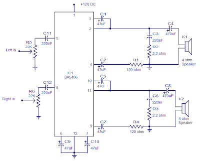

