Tuesday 8 October 2013
Electronic Fuse for DC Short Circuit Protection
This is an electronic fuse that protects the load against short circuit.
Project Description
Relays must be chosen with a voltage value equals to the input voltage. Don’t omit using the 100uF capacitor with appropriate voltage value with respect to the input voltage. If you can’t provide, you can use C106 instead of BRX46.
 You can adjust the current with using 10K potentiometer. If you will use the fuse with very high currents, lower the 0R6 5W resistor value (ex. 0R47, 0R33, 0R22 or 0R1). Watt value of the resistor should be increased also.
Project Description
Relays must be chosen with a voltage value equals to the input voltage. Don’t omit using the 100uF capacitor with appropriate voltage value with respect to the input voltage. If you can’t provide, you can use C106 instead of BRX46.
Sunday 6 October 2013
Simple Darkness Activated Alarm
Most darkness activated alarms employ opamps and some logic ICs. Here, a less expensive approach is shown based on the eternal 555, this time in monostable multivibrator mode. Components R2 and C1 represent a one-second network. When the LDR (light dependent resistor) is in the dark, its resistance is high, pulling pin 2 of the 555 to ground. This triggers the monostable and the (active!) 6-volt piezo buzzer will sound. Preset P1 is adjusted depending on ambient light levels. The circuit may be fitted on a wall in your home. Assuming P1 has been set for the existing ambient light level, the shadow cast by anybody entering the room or hallway will trigger the alarm.

ContinueReading..
Friday 4 October 2013
Fuse Box BMW Z4 Coupe Under The Right Side 2007 Diagram
Fuse Box BMW Z4 Coupe Under The Right Side 2007 Diagram - Here are new post for Fuse Box BMW Z4 Coupe Under The Right Side 2007 Diagram.
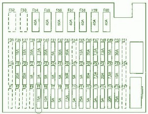

Fuse Panel Layout Diagram Parts: low beam headlight, brake light, side light interior indicator, airbag, cd player, central locking system, cigar lighter, interior and luggage, comp lights, lighting circuit.
ContinueReading..
Fuse Box BMW Z4 Coupe Under The Right Side 2007 Diagram


Fuse Panel Layout Diagram Parts: low beam headlight, brake light, side light interior indicator, airbag, cd player, central locking system, cigar lighter, interior and luggage, comp lights, lighting circuit.
Wednesday 2 October 2013
30mA LED Dimmer
If you’ve ever tried dimming a LED with a simple potentiometer, you know that the approach does not work very well. Just as with ordinary diodes, the voltage-current characteristic of LEDs is far from linear. The result - depending on the potentiometer setting the LED brightness will hardly change most of the time as the pot is turned and a sudden variation at the end. The best method to tackle this problem is to power the LED from a current source with zero to 100% adjustment range. The circuit shown here is an example. A low-current LED (D1) is used to generate a reference voltage that’s first buffered by one half of an LM358. The actual current source that powers the LED(s) is built around the second opamp in the chip.

The potentiometer allows the output current to be adjusted, with R2 acting as a current sense, the resistor dropping the same voltage as the one obtained from the pot. Using Ohm’s law we find that the maximum current through R2 amounts to about 29 mA (I LED = 1.6 V / 56 Ω). If necessary, the current may be adapted to suit other LED types, for example, 20 mA is obtained with R2 = 82 Ω and 10 mA at R2 = 150 Ω. It is also possible to connect several LEDs in series. The total voltage available for the LEDs is determined by the voltage drop across series resistor and the opamp, and, of course, the supply voltage.
In this way, the highest number of LEDs may be found from ULED, total = Ubatt – 5.1 V. In principle, it is possible to increase the supply voltage to 30 V in order to connect even more LEDs in series. This does, however, call for the value of series resistor R1 to be increased to prevent overloading the low-current LED used in the voltage reference. If you intend to experiment with larger numbers of LEDs (say, in arrays) then the maximum loading of the opamps becomes an issue. The DIP version of the LM358 may dissipate up to 830 mW. The power, P, is calculated from P = Ubatt – 1.6 – ULED,total × I LED,max.
ContinueReading..
The potentiometer allows the output current to be adjusted, with R2 acting as a current sense, the resistor dropping the same voltage as the one obtained from the pot. Using Ohm’s law we find that the maximum current through R2 amounts to about 29 mA (I LED = 1.6 V / 56 Ω). If necessary, the current may be adapted to suit other LED types, for example, 20 mA is obtained with R2 = 82 Ω and 10 mA at R2 = 150 Ω. It is also possible to connect several LEDs in series. The total voltage available for the LEDs is determined by the voltage drop across series resistor and the opamp, and, of course, the supply voltage.
In this way, the highest number of LEDs may be found from ULED, total = Ubatt – 5.1 V. In principle, it is possible to increase the supply voltage to 30 V in order to connect even more LEDs in series. This does, however, call for the value of series resistor R1 to be increased to prevent overloading the low-current LED used in the voltage reference. If you intend to experiment with larger numbers of LEDs (say, in arrays) then the maximum loading of the opamps becomes an issue. The DIP version of the LM358 may dissipate up to 830 mW. The power, P, is calculated from P = Ubatt – 1.6 – ULED,total × I LED,max.
Subscribe to:
Posts (Atom)