Friday, 31 May 2013
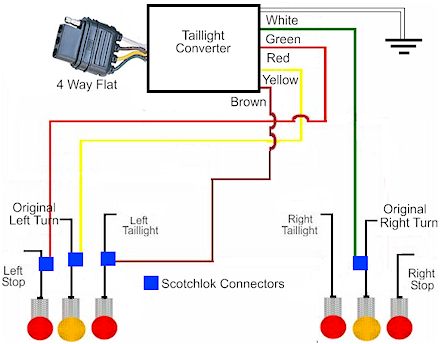
Installtrailer Light Taillight Converter Towing

Cassette Cd And 6 Speakers Audio System Wiring Circuit Schematic.

Here Is The Wiring Diagram For The Trailer Lights.

Jeep Grand Cherokee Radio Adaptor Wiring Harness Circuit Schematic.

Pin Hd Trailer Wiring Diagram Truck Side Ford Truck Enthusiasts.

250 And 525 Sx Mxc Exc Electrical System And Wiring Diagram Here.

Honda Pilot Wiring Harness And Wiring Color Code Circuit Schematic.

Gm Trailer Wiring Harness Gm Trailer Wiring Harness Manufacturers In.

How To Install A Trailer Light Taillight Converter In Your Towing.

20 Wishbone Flat 4 Trailer Wiring Harness 108820.

Toyota Automatic Transmission A340e Shift Lock System Wiring Diagram.
Friday, 17 May 2013
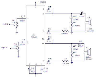
Stereo Amplifier Circuit with BA5406
 Stereo Amplifier Circuit with BA5406
In the this circuit diagram, BA5406 is configured to deliver 5 x 2 watts at 4 ohm speakers to a supply voltage of 9 volts. The capacitor C3 is a power supply filter capacitor. C11 and C12 are decoupling capacitors DC input for the left and right. C3 and R2 form a Zobel network to output the left, while C6 and R3 is the same for the right channel.
Zobel network purpose is to reduce vibrations and improve the high frequency stability of the amplifier. Potentiometers R5 and R6 serves as a volume control for left and right channels. C8 pair CapacitorsC4 and the amplifier outputs to the speakers. C9 and C10 are the noise filtering capacitors. C1 and C5 are starting capacitors for left and right channels.
Zobel network purpose is to reduce vibrations and improve the high frequency stability of the amplifier. Potentiometers R5 and R6 serves as a volume control for left and right channels. C8 pair CapacitorsC4 and the amplifier outputs to the speakers. C9 and C10 are the noise filtering capacitors. C1 and C5 are starting capacitors for left and right channels.
Notes.
- BA5406 requires a proper heat sink.
- Supply voltage range is 5 to 15V DC.
- I used 9V DC for powering the amplifier.
- The power supply must be well regulated and filtered
Sunday, 5 May 2013
The Audio Video Distribution Amplifier
With the amount of equipment in home entertainment centers today the need to be able to vary the gain of the audio or video signal is needed. I found this particular circuit helpful when used in conjunction with the Universal Descrambler and a Stabilizer circuit I built for making copies of video tapes. It not only allowed me the ability to fine tune the video strength it also helped me increase the recorded audio which typically becomes poor when making tape copies. Circuit operation is straight forward for amplifier circuits. The second channel for the audio amplifier is made up of the same components except the other half of IC1 is used. Pin 6 & 5 are inputs and 7 is the output.
Circuit Diagram


Circuit Diagram


Subscribe to:
Comments (Atom)