Showing posts with label circuit. Show all posts

Thursday, 19 December 2013

Super Digital Combination lock Circuit Diagram


The circuit above above makes use of the CMOS 4017 decade counter IC. Each depression of a switch steps the output through 0– 9. By coupling the output via an AND gate to the next IC, apredefined code has to be input to create the output. Each PBSswitch is debounced by tw1o gates of a CMOS4001 quad 2-input NORgate. This ensures a clean pulse to the input of each CMOS4017 counter. Only when the correct number of presses at PBS Awill allow PBS B to become active. This is similar for PBS C andPBS D. At IC4, PBS D must be pressed 7 times. Then PBS C is againpressed 7 times, stepping from output 1 to output 8. The ANDgate formed around CMOS4081 then goes high, lighting the LED. TheReset switch can be pressed at any time. Power on resetis provided by the 100n capacitor near the reset switch. Below isa picture of one that I made about 15 years ago:  

Super Digital Combination lock Circuit Diagram


Unfortunately, this board was part of a much larger project containing multiple power supplies. One day whilst working on another circuit , I slipped with a wire and splashed 24volts DConto this board. There was a small spark, and puff of smoke before all this chips were cooked! If anyone does consider building such a circuit, then my advice would be to stop and lookin your local electronic parts catalogue. There are now dedicated combination lock IC`s with combinations many time sgreater than this circuit. Incidentally the number of combinations offered here is 10 x 10 x 10 x 10 x 9 = 90,000.Check out Dean White`s Electronic Gadgets, on the Electronic Sites Alliance web ring, he also has a combination lock circuit.
ContinueReading..

Tuesday, 8 October 2013

Electronic Fuse for DC Short Circuit Protection

This is an electronic fuse that protects the load against short circuit.

Project Description

Relays must be chosen with a voltage value equals to the input voltage. Don’t omit using the 100uF capacitor with appropriate voltage value with respect to the input voltage. If you can’t provide, you can use C106 instead of BRX46.
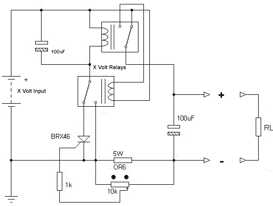
Circuit Project: Electronic Fuse for DC Short Circuit Protection by BRX46
You can adjust the current with using 10K potentiometer. If you will use the fuse with very high currents, lower the 0R6 5W resistor value (ex. 0R47, 0R33, 0R22 or 0R1). Watt value of the resistor should be increased also.
ContinueReading..

Wednesday, 12 June 2013

VHF UHF Low Noise booster circuit

VHF UHF Low-Noise amplifiers circuit can be designed using the MAX2664 and MAX2665 ultra-compact LNAs for VHF UHF applications.These devices incorporate a broadband LNA with an integrated bypass switch. The MAX2664 covers the UHF frequency range from 470MHz to 860MHz, and the MAX2665 covers the VHF frequency range from 75MHz to 230MHz. Each device has a zero-power bypass mode for improved high-signal-level handling conditions.Both ICs has a high gain around 15dB and require a single power supply , that can provide an output voltage between 2.4 to 3.5 volts .VHF UHF Low-Noise amplifiers has a very low current consumption of 3.3 mA and can be used in applications like : Smartphones/Handsets , MP3 Players , Home Audio/Video and other portable navigation devices .


VHF UHF Low-Noise booster circuit
ContinueReading..

Friday, 17 May 2013

Stereo Amplifier Circuit with BA5406
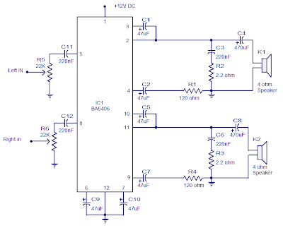
Stereo Amplifier Circuit with BA5406Stereo Amplifier Circuit with BA5406

In the this circuit diagram, BA5406 is configured to deliver 5 x 2 watts at 4 ohm speakers to a supply voltage of 9 volts. The capacitor C3 is a power supply filter capacitor. C11 and C12 are decoupling capacitors DC input for the left and right. C3 and R2 form a Zobel network to output the left, while C6 and R3 is the same for the right channel.

Zobel network purpose is to reduce vibrations and improve the high frequency stability of the amplifier. Potentiometers R5 and R6 serves as a volume control for left and right channels. C8 pair CapacitorsC4 and the amplifier outputs to the speakers. C9 and C10 are the noise filtering capacitors. C1 and C5 are starting capacitors for left and right channels.

Notes.
  • BA5406 requires a proper heat sink.
  • Supply voltage range is 5 to 15V DC.
  • I used 9V DC for powering the amplifier.
  • The power supply must be well regulated and filtered
ContinueReading..

Wednesday, 27 March 2013

Non Contact Power Monitor circuit

Here is a simple non-contact AC power monitor for home appliances and laboratory equipment that should remain continuously switched-on. A fuse failure or power breakdown in the equipment going unnoticed may cause irreparable loss. The monitor sounds an alarm on detecting power failure to the equipment. The circuit is built around CMOS IC CD4011 utilising only a few components. NAND gates N1 and N2 of the IC are wired as an oscillator that drives a piezobuzzer directly. Resistors R2 and R3 and capacitor C2 are the oscillator components. The amplifier comprising transistors T1 and T2 disables the oscillator when mains power is available. In the standby mode, the base of T1 picks up 50Hz mains hum during the positive half cycles of AC and T1 conducts.

Circuit diagram:

    Non-Contact Power Monitor circuit diagram

Non-Contact Power Monitor circuit diagram  

This provides base current to T2 and it also conducts, pulling the collector to ground potential. As the collectors of T1 and T2 are connected to pin 2 of NAND gate N1 of the oscillator, the oscillator gets disabled when the transistors conduct. Capacitor C1 prevents rise of the collector voltage of T2 again during the negative half cycles. When the power fails, the electrical field around the equipment’s wiring ceases and T1 and T2 turn off. Capacitor C1 starts charging via R1 and preset VR and when it gets sufficiently charged, the oscillator is enabled and the piezobuzzer produces a shrill tone. Resistor R1 protects T2 from short circuit if VR is adjusted to zero resistance.

The circuit can be easily assembled on a perforated/breadboard. Use a small plastic case to enclose the circuit and a telescopic antenna as aerial. A 9V battery can be used to power the circuit. Since the circuit draws only a few microamperes current in the standby mode, the battery will last several months. After assembling the circuit, take the aerial near the mains cable and adjust VR until the alarm stops to indicate the standby mode. The circuit can be placed on the equipment to be monitored close to the mains cable.

ContinueReading..