Showing posts with label stereo. Show all posts
Showing posts with label stereo. Show all posts
Monday, 23 December 2013
11 W Stereo or 22 W Mono Power Amp
Integrated AF power amps have seen great improvements in recent years offering improved power and easier use. The TDA1519C from Philips contains two power amplifiers providing 11 W per channel stereo or 22 W mono when the two channels are connected in a bridge configuration. The special in-line SIL9P package outline allows the chip to be conveniently bolted to a suitable heatsink. The TDA1519CSP is the SMD version, in this case the heat sink is mounted over, and in contact with, the top surface of the chip.
11W Stereo Amplifier Circuit Diagram
11W Stereo Amplifier Circuit Diagram

The operating voltage of this device is from +6V to +17.5V. The two channels of the amplifier are different in that one channel, between pins 1 and 4, is a non-inverting amplifier, while the other between pins 9 and 6 is an inverting amplifier. It is therefore necessary in stereo operation, to wire the speakers so that one of them has its polarity reversed. Each amplifier has an input impedance of 60kΩ and a voltage gain of 40dB, i.e. 100 times. When both amplifier are used in a bridge configuration, the inputs are in parallel so that the input impedance will be 30kΩ.
22W Stereo Amplifier Circuit Diagram
22W Stereo Amplifier Circuit Diagram

A combined mute/standby function is provided on pin 8. In its simplest form this can be connected to the positive rail via a switch. When the switch is open the amplifier will be in standby mode and current consumption is less than 100µA. When the switch is closed, the amplifier will be operational. A circuit is also shown that uses the mute input to prevent the annoying switch-on plop heard when power amps are first switched on This is caused by the rush of current to charge capacitors C1 and C2.
Mute/Standby Switch Circuit Diagram
Mute/Standby Switch Circuit Diagram

The circuit shown generates a ramp voltage, which is applied to pin 8. At switch on, as the voltage rises from 3.3 V to 6.4 V, the amplifier will switch out of standby mode and into mute mode allowing C1 and C2 to charge. Only when the ramp voltage on pin 8 reaches 8.5V will the amplifier switch into active mode. Protection built into the TDA1519C would seem to make it almost foolproof. The two outputs can be shorted to either of the supply rails and to each other. A thermal shutdown will prevent overloading and the power supply input is protected against accidental reversal of the supply leads up to 6V.
Source: http://www.ecircuitslab.com/2011/07/11-w-stereo-or-22-w-mono-power-amp.html

Friday, 17 May 2013
Stereo Amplifier Circuit with BA5406
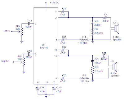 Stereo Amplifier Circuit with BA5406
In the this circuit diagram, BA5406 is configured to deliver 5 x 2 watts at 4 ohm speakers to a supply voltage of 9 volts. The capacitor C3 is a power supply filter capacitor. C11 and C12 are decoupling capacitors DC input for the left and right. C3 and R2 form a Zobel network to output the left, while C6 and R3 is the same for the right channel.
Zobel network purpose is to reduce vibrations and improve the high frequency stability of the amplifier. Potentiometers R5 and R6 serves as a volume control for left and right channels. C8 pair CapacitorsC4 and the amplifier outputs to the speakers. C9 and C10 are the noise filtering capacitors. C1 and C5 are starting capacitors for left and right channels.
Zobel network purpose is to reduce vibrations and improve the high frequency stability of the amplifier. Potentiometers R5 and R6 serves as a volume control for left and right channels. C8 pair CapacitorsC4 and the amplifier outputs to the speakers. C9 and C10 are the noise filtering capacitors. C1 and C5 are starting capacitors for left and right channels.
Notes.
- BA5406 requires a proper heat sink.
- Supply voltage range is 5 to 15V DC.
- I used 9V DC for powering the amplifier.
- The power supply must be well regulated and filtered
Subscribe to:
Posts (Atom)