Sunday, 22 September 2013
12 Volt DC Fluorescent Lamp Driver
A number of people have been unable to find the transformer needed for the Black Light project, so I looked around to see if I could find a fluorescent lamp driver that does not require any special components. I finally found one in Electronics Now. Here it is. It uses a normal 120 to 6V stepdown transformer in reverse to step 12V to about 350V to drive a lamp without the need to warm the filaments.
 Parts:
C1 100uf 25V Electrolytic Capacitor
C2,C3 0.01uf 25V Ceramic Disc Capacitor
C4 0.01uf 1KV Ceramic Disc Capacitor
R1 1K 1/4W Resistor
R2 2.7K 1/4W Resistor
Q1 IRF510 MOSFET
U1 TLC555 Timer IC
T1 6V 300mA Transformer
LAMP 4W Fluorescent Lamp
MISC Board, Wire, Heatsink For Q1
Notes:
ContinueReading..
 Parts:
C1 100uf 25V Electrolytic Capacitor
C2,C3 0.01uf 25V Ceramic Disc Capacitor
C4 0.01uf 1KV Ceramic Disc Capacitor
R1 1K 1/4W Resistor
R2 2.7K 1/4W Resistor
Q1 IRF510 MOSFET
U1 TLC555 Timer IC
T1 6V 300mA Transformer
LAMP 4W Fluorescent Lamp
MISC Board, Wire, Heatsink For Q1
Notes:
- Q1 must be installed on a heat sink.
- A 240V to 10V transformer will work better then the one in the parts list. The problem is that they are hard to find.
- This circuit can give a nasty (but not too dangerous) shock. Be careful around the output leads.

Friday, 20 September 2013
1995 KLR650 Dual Sport Motocross Wiring Diagram
 | |
| 1995 KLR650 Dual Sport Motocross Wiring Diagram |
The Part of 1995 KLR650 Dual Sport Motocross Wiring Diagram: instrument cluster, ignition switch,
right front turn signal, front brake light switch, starter button, engine stop switch, water temperature sender, meter light, high beam indicator light, neutral indicator light, fan switch, cooling fan, voltage regulator rectifier, turn signal relay, brake tail light, license light, starter circuit relay, battery, chassis ground, starter relay, CDI, neutral switch, magneto, headlight switch, dimmer switch, turn signal switch, horn button, stand switch, ignition pick up coil, chassis ground, horn, headlight, turn signal.
Tuesday, 10 September 2013
An LCD Clock Kit Suitable for Beginners with Open Source Arduino Firmware
Simpleclock is an easy to assemble attractive 4-digit 7-segment LED display clock with temperature and alarm function. It is available in three display colors: Red, Blue and White. It comes as a kit of through-the-hole parts and can be soldered by any person with basic soldering experience. An attractive acrylic stand is included.

Wednesday, 12 June 2013
VHF UHF Low Noise booster circuit
VHF UHF Low-Noise amplifiers circuit can be designed using the MAX2664 and MAX2665 ultra-compact LNAs for VHF UHF applications.These devices incorporate a broadband LNA with an integrated bypass switch. The MAX2664 covers the UHF frequency range from 470MHz to 860MHz, and the MAX2665 covers the VHF frequency range from 75MHz to 230MHz. Each device has a zero-power bypass mode for improved high-signal-level handling conditions.Both ICs has a high gain around 15dB and require a single power supply , that can provide an output voltage between 2.4 to 3.5 volts .VHF UHF Low-Noise amplifiers has a very low current consumption of 3.3 mA and can be used in applications like : Smartphones/Handsets , MP3 Players , Home Audio/Video and other portable navigation devices .

VHF UHF Low-Noise booster circuit
ContinueReading..
VHF UHF Low-Noise booster circuit
Sunday, 2 June 2013
Brake Control Future Reference Generic Wiring Diagram

Terminal Number Function 7 Core Wire Colour 1 Indicator Left Yellow 2.

Jeep Grand Cherokee Radio Adaptor Wiring Harness Circuit Schematic.

Trailer Wiring Testers 1 Jpg.

With The Brake Control For Future Reference Generic Wiring Diagram.

Provided 2 Extra Connections Compared To A Standard 4 Wire.

Way 7 Pole Rv Travel Trailer Connector Wiring Color Code.

Trailer Wiring Electrical Connections Are Used On Car Boat And.

Trailer Wiring Diagrams Pinouts.

There Here Is The Wiring Diagram For The Trailer Wiring For Your Truck.

79088 Trailer Lights Wiring Harness Trailer Wiring Bmp.
Friday, 31 May 2013
Installtrailer Light Taillight Converter Towing

Cassette Cd And 6 Speakers Audio System Wiring Circuit Schematic.

Here Is The Wiring Diagram For The Trailer Lights.
Jeep Grand Cherokee Radio Adaptor Wiring Harness Circuit Schematic.

Pin Hd Trailer Wiring Diagram Truck Side Ford Truck Enthusiasts.

250 And 525 Sx Mxc Exc Electrical System And Wiring Diagram Here.

Honda Pilot Wiring Harness And Wiring Color Code Circuit Schematic.

Gm Trailer Wiring Harness Gm Trailer Wiring Harness Manufacturers In.

How To Install A Trailer Light Taillight Converter In Your Towing.

20 Wishbone Flat 4 Trailer Wiring Harness 108820.

Toyota Automatic Transmission A340e Shift Lock System Wiring Diagram.
Friday, 17 May 2013
Stereo Amplifier Circuit with BA5406
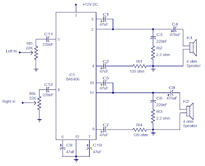 Stereo Amplifier Circuit with BA5406
In the this circuit diagram, BA5406 is configured to deliver 5 x 2 watts at 4 ohm speakers to a supply voltage of 9 volts. The capacitor C3 is a power supply filter capacitor. C11 and C12 are decoupling capacitors DC input for the left and right. C3 and R2 form a Zobel network to output the left, while C6 and R3 is the same for the right channel.
Zobel network purpose is to reduce vibrations and improve the high frequency stability of the amplifier. Potentiometers R5 and R6 serves as a volume control for left and right channels. C8 pair CapacitorsC4 and the amplifier outputs to the speakers. C9 and C10 are the noise filtering capacitors. C1 and C5 are starting capacitors for left and right channels.
Zobel network purpose is to reduce vibrations and improve the high frequency stability of the amplifier. Potentiometers R5 and R6 serves as a volume control for left and right channels. C8 pair CapacitorsC4 and the amplifier outputs to the speakers. C9 and C10 are the noise filtering capacitors. C1 and C5 are starting capacitors for left and right channels.
Notes.
- BA5406 requires a proper heat sink.
- Supply voltage range is 5 to 15V DC.
- I used 9V DC for powering the amplifier.
- The power supply must be well regulated and filtered
Subscribe to:
Posts (Atom)